Complete Guide to Plastic Injection Mold Tooling

In custom plastic manufacturing, your final product is only as precise as the tool that forms it. Plastic injection mold tooling represents the primary capital investment in any custom molding program. A expertly engineered mold operates seamlessly for millions of cycles at tight tolerances, while a sub-optimal tool leads to chronic line stoppages, excessive flash, warping, and costly tool repairs.
Beyond simply cutting a shape into metal, an injection mold is a precision heat exchanger and high-pressure vessel. Understanding the core mechanical systems inside a mold helps OEM engineering and procurement teams make smarter tooling decisions.
1. The Core Anatomy of an Injection Mold
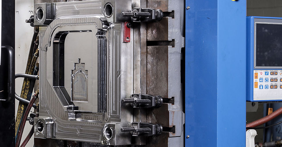
During operation, an injection mold must withstand clamping forces ranging from 50 to over 1,000 tons while channeling molten resin under extreme pressure. Every production tool consists of several integrated mechanical sub-systems:
Fixed Half (A-Side): Mounted to the stationary platen of the press, this side contains the sprue bushing where plastic enters from the injection unit.
Moving Half (B-Side): Mounted to the moving platen, this side opens and closes during every cycle and houses the mechanical ejection system.
Core and Cavity Inserts: Precision-machined block inserts that define the shape of the part. The cavity forms the exterior surface, while the core forms the interior features.
Ejection Assembly: Driven by hydraulic or electric press actuators, ejector pins, stripper plates, or air-blast valves push the solidified part off the core once the mold opens.
2. Runner Topology: Hot Runner vs. Cold Runner Systems
How molten plastic travels from the press nozzle to the individual part cavities impacts part quality, cycle speed, and material scrap rates.
Feature | Cold Runner Systems | Hot Runner Systems |
Mechanical Setup | Channels are cut into the tool face; plastic in runners solidifies every cycle. | Heated manifold keeps resin molten inside the tool up to the gate. |
Material Efficiency | Produces runner scrap (which can often be reprocessed as plastic regrind). | Zero runner scrap; 100% of injected material becomes usable parts. |
Cycle Speed | Slower; cycle time is limited by the thickness of the cooling runner. | Faster; no runner to cool, significantly reducing hold and cooling time. |
Tooling Investment | Lower upfront tooling cost; simple mechanical design. | Higher initial tool cost; requires temperature controllers and valved gating. |
Best Application | Short runs, frequent color changes, simple single/multi-cavity tools. | High-volume production runs, automotive components, multi-cavity electronic housings. |
3. Cooling Channel Topology: The Key to Cycle Time & Part Flatness
Cooling accounts for up to 70% of the total injection molding cycle time. If heat is dissipated unevenly across the tool face, differential shrinkage causes internal stress, sink marks, and part warping.
Advanced tooling designs incorporate engineered water line circuits that maintain uniform steel temperatures:
Conventional Drilled Cooling: Straight-line water channels drilled through the steel blocks.
Baffles and Bubblers: Internal fittings inserted into deep core pins to force coolant into hard-to-reach tool areas.
Conformal Cooling: 3D-printed metal inserts with curved cooling channels that closely follow complex part contours, drastically reducing cycle times on intricate geometries.
4. Selecting the Right Tooling Class & Steel Grade
The mechanical complexity and metal selection of your tool should directly align with your anticipated production volumes and resin aggressiveness:
Part Architecture & Layout: For a complete comparison between single-cavity, multi-cavity, and family mold layouts, review our guide on injection molding tool options for plastic parts.
Hardened Tool Steel Selection: To evaluate specific metal grades (such as H13, P20, or 420 Stainless Steel) for glass-filled or abrasive resins, explore our deep dive on high-performance injection molding tools and tool steel selection.
SPI Tooling Standards: Learn how tooling specs are categorized from prototype to 1-million+ cycle tools in our overview of the 5 types of SPI mold classifications.
5. Preventive Tool Maintenance & Mold Longevity
A production mold is a long-term asset. To ensure your tooling delivers consistent dimensional accuracy over its full rated lifespan, molder engineering teams must execute routine preventive maintenance:
Bench Inspections & Cleaning: Periodically stripping residual resin off parting lines and venting channels to prevent gas buildup and parting-line flash.
Water Line Descaling: Flushing cooling channels with rust inhibitors to clear mineral deposits and maintain thermal conductivity.
Lubrication & Wear Audit: Inspecting slides, lifters, and leader pins for friction wear or gelling.
If you are transferring existing tooling from an underperforming supplier, our mold tool transfer protocol ensures your active steel undergoes full bench inspection, water flow testing, and First Article CMM layout before entering production.
Partnering with an Engineering-Led Molder
Investing in high-quality plastic injection mold tooling up front safeguards your program against expensive downtime and quality defects down the road. Whether you are launching a new product or optimizing an active tool, Moraine Plastics provides full lifecycle support.
Review our full plant processing and tooling capabilities, explore our Wisconsin facility, or contact our tooling engineers today to request a DFM tool design review.